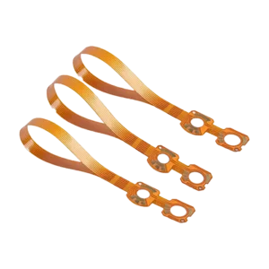
High Frequency RF PCB
$84.50
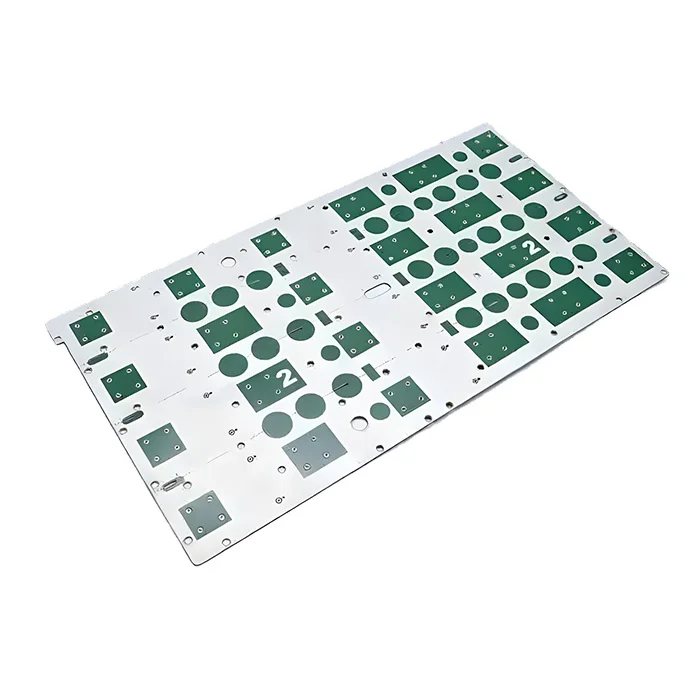
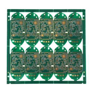
High-frequency RF PCB is specifically designed for RF systems such as cellular networks. 5G, aerospace radar systems, which require stable signal transmission over long distances at high frequency. High-frequency PCBs help RF systems minimize signal loss, interference, and phase distortion, ensuring high performance and good network speed and coverage.
Shipping fee and delivery date to be negotiated. Send inquiry for more details.
Your payment information is processed securely. We do not store credit card details nor have access to your credit card information.
Claim a refund if your order is missing or arrives with product issues, our support team would deal with your refund within 24 hours.
| Layer Counts | 4L |
| Base Material | Rogers |
| Board Thickness(mm) | 1.2mm |
| Max board size(mm) | 570*850mm |
| PCB size tolerance | ±0.2mm |
| Min. Hole Size | 0.15mm |
| Min. Line Width | 4mil |
| Copper Weight | 1oz |
| Surface Finish | ENIG |
| Certificate | UL, IPC-6012, RoHS, ISO 9001, ISO14001 |
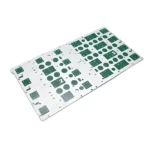 High Frequency RF PCB
| 5 star | 0% | |
| 4 star | 0% | |
| 3 star | 0% | |
| 2 star | 0% | |
| 1 star | 0% |
Sorry, no reviews match your current selections
Questions & Answers
1. Does MOKOPCB support mass production?
Yes, we have the capacity to handle small to high-volume PCB production with automated assembly lines.
2. Where does MOKOPCB ship from and to?
We deliver our goods from our facilities in Shenzhen, China.
3. Why are RF PCBs more expensive than standard PCBs?
RF PCBs cost more mainly because of specialized low-loss materials, stricter manufacturing, and testing requirements. Commonly used HF PCB material is Rogers, which is expensive than FR4. And some production processes, like laser drilling and precise impedance control, need to maintain signal integrity at high frequencies, adding production costs compared to standard PCBs.
4. What materials are available for your RF HF PCBs?
Rogers, PTFE-based(eg, Teflon), Rogers+ FR4 hybrid constructions are available for RF HF PCBs. Rogers is the most popular one.
5. What frequency range does your HF PCB support for RF systems?
Modern HF PCBs for RF systems typically support frequencies from sub-6 GHz to mmWave spectrum(30 GHz and above).
6. Which surface finish is best for the HF RF PCB?
ENIG is the most common one due to its smooth surface finish and oxidation resistance. Immersive silver is another good choice with relatively low RF loss.
7. Do you help optimize my RF PCB layout?
Yes, our engineering team provides full RF PCB layout optimization services. From impedance routing, ground plane optimization, to proper grounding and shielding, we will validate the design to meet the best performance before production.
8. Why is my RF output power unstable at high frequencies?
Power instability may come from impedance mismatches, thermal effects, or layout issues. It may need to optimize the transmission line design, improve thermal management, and ensure proper grounding. Contact us and our experts are able to analyze the root cause of your RF PCB.

