Plated-Through Slots
Plated-through slots are essential PCB design features that offer reliable mounting and electrical connectivity for components with rectangular or irregularly shaped leads. In contrast to conventional round holes, which are applicable only to standard cylindrical pins, plated slots guarantee an enhanced fit and better mechanical stability for components with non-standard shapes.
Since electronic devices have been shrinking in size and component varieties have been rising, the need for plated-through slots has also increased. They facilitate the mounting of versatile components and provide electrical stability in high-density designs.
In this article, we will explore their definition, benefits, design considerations, and manufacturing process.
What Are Plated-through Slots?
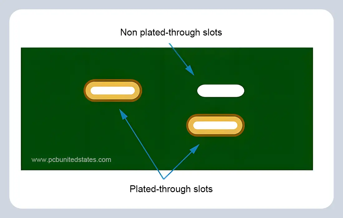
A plated-through slot (PTS) is an opening in a circuit board that is usually shaped rectangular or oval. It is electroplated along the sides to provide an electrical connection between layers and can also serve as a space for assembling components. Unlike unplated slots, which are simply cutouts, plated-through slots have both a mechanical (e.g., fitting rectangular leads) and electrical function. They find common use in connectors, switches and specialized components to enhance assembly efficiency and product durability.
Benefits of Using Plated-through Slots
Plated-through slots offer better solutions for mounting components with non-circular leads than the conventionally used round holes, which tend to cause inefficient use of board space. The key benefits include:
- Elimination of additional spacing between component pins and the PCB, thus a more compact and efficient layout can be achieved.
- Minimization of solder joint defects through proper fit between rectangular component leads and the openings, eliminating voids that may obstruct electrical interconnection.
- Allowing precise lead placement, which helps free up additional space on the PCB surface.
How to Define Plated-Through Slots in PCB Design Files?
When designing PCBs, the exact length and width of every plated-through slot should be stated and this should be reflected in the manufacturing drawing so that they can be manufactured accurately.
In EDA software, an elliptical hole can be used to represent a plated-through slot. Slots can also be defined within the Gerber mechanical layer. If the design file lacks a mechanical layer, one should be added to define the slot. In addition, it would be advisable to have a README file to describe the slot requirements in a clear way.
Step-by-Step Process for Creating Plated-through Slots
Step 1: Mill the slots to the required dimensions. The unwanted copper on the board is removed by this process to create the required traces, pads, and so on, based on the layout design.
Step 2: Drill the slots using the appropriate drilling method based on the specific design requirements.
Step 3: Clean the slots thoroughly to remove any drilling residues or debris that may have accumulated during the milling and drilling processes.
Step 4: Apply copper plating to the slots using the same electroless copper deposition method used for plating through-holes. This creates the conductive coating inside the slots.
Step 5: Apply the final surface finish to complete the plated-through slot fabrication process.
The Capability of the Plated Slot at MOKOPCB
MOKOPCB specializes in manufacturing precise plated-through slots to meet different application requirements. Our superior drilling and plating facilities guarantee correct slot dimensions, smooth edges, and uniform copper plating to provide the best conductivity and durability. We can fabricate plated slots in various shapes and sizes with tolerances that comply with IPC standards. For both prototype work and large-volume runs, our engineers collaborate with customers to ensure that their plated-through slot designs are optimized to meet performance, manufacturability, and cost requirements.
To give you a clear view of our capabilities, here are the standard tolerances for plated holes and slots at MOKOPCB:
| Item | Capability |
| PCB through-hole diameter | 0.15 mm – 6.0 mm+ |
| PCB through-hole diameter tolerance |
PTH: +0.08/−0 mm to +0.30/−0 mm (depending on size) NPTH: ±0.05 mm |
| Min. tolerance for drilled slot holes |
Slot width direction: ±0.1 mm Slot length direction: ±0.15 mm |
| Min. tolerance for milled slot holes | Slot width & slot length direction: ±0.15 mm |
Contact Us
Got any questions or inquiries? Fill out the form and we will get back to you soon