The assembly process involves installing the necessary components on the blank PCB. There are two commonly used methods: SMT vs. THT. Both feature distinct characteristics and pros and cons. We will examine how SMT and THT vary from one another in this blog and explore the important aspects to take into account when making a decision. After reading this blog, you may find a suitable option for your next project.
SMT vs. THT: A Brief Overview
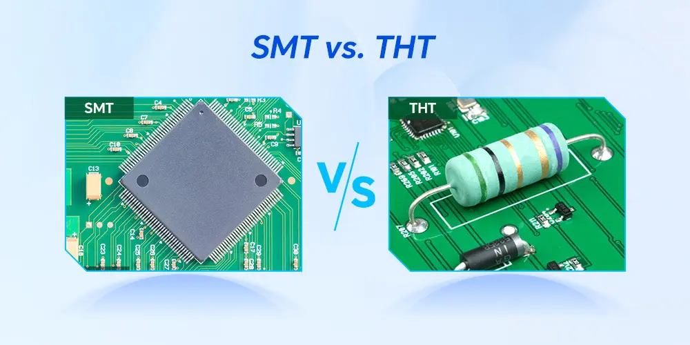
SMT, or surface mount technology, directly mounts the SMD components on the surface of the circuit board. Surface-mount technology is an efficient and automated technology that can achieve a more compact and lighter final product. It is highly different from traditional assembly technology which is THT.
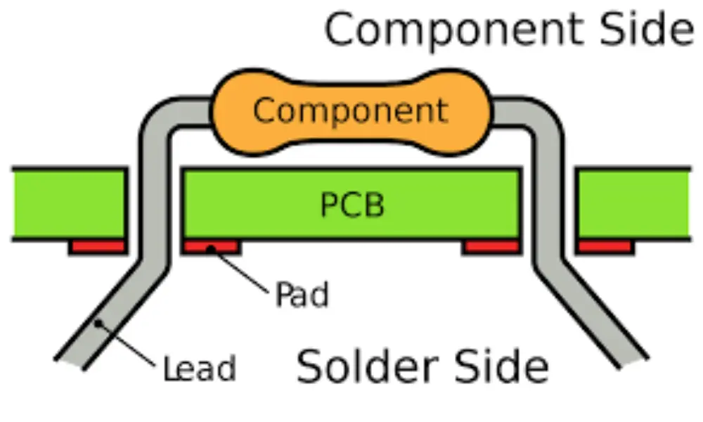
THT refers to through-hole technology, which calls for soldering the component leads on the opposite side after they have been inserted into the PCB’s drill holes. This is an assembly method that relies heavily on manual labor. The difference between the two assembly methods will affect many aspects such as PCB design, materials used, manufacturing processes, and labor costs.
Top 5 Differences Between SMT and THT Assembly
Knowing the distinctions between SMT vs. THT is crucial for everyone employed in the electronics sector. Below, we will reveal the top 5 differences between them to help you clear up any confusion.
Assembly Process
The assembly processes of SMT vs. THT are fundamentally different in key production stages, from component placement to soldering techniques. Here are the differences in the key process.
Key process of surface mount technology:
Apply solder paste – The printer automatically applies the solder paste to the pad precisely through the PCB stencil.
Component placement – Then, the pick-and-place machines can place the small SMD components at high speed into the designated locations where the solder has been applied.
Reflow soldering – Once all the components are put on the pad. The board is sent through a reflow oven to melt the solder and form strong connections.
Key process of through hole technology:
Component insertion – THT components with long leads need to be inserted into the pre-drilled hole on the board. This procedure can be carried out manually or automatically.
Wave soldering/Hand soldering – The PCB passes through the wave-like molten solder, and the leads and pads can simultaneously form strong connections. Also, the components can be soldered by hand one by one.
Component Characteristics
The components of SMT vs. THT look very different. SMT components are usually small and light, achieving a more compact design. Due to their small solder joints, SMD components are more susceptible to thermal stress and vibration. Conversely, THT components are large and heavy which perform well at high temperature and vibration environments. The leads pass through the holes, forming strong mechanical bonds.
Performance and Reliability
SMT assembly process has a high degree of automation, providing high quality and consistent results. The solder paste applied by the printer will form a good electrical and mechanical connection between the components and pads. However, the components’ reliability will affected by the accuracy of component placement and the quality of the solder paste application.
Through-hole assembly is a mature process with fewer issues affecting soldering quality and can form a strong mechanical connection. However, parasitic inductance and capacitance may rise due to the components’ size and longer leads. This will degrade performance at high frequencies.
Cost Structure Difference
SMT vs. THT have drastically different cost structures due to their assembly process. SMT should initial high investment in automated machines such as printers, reflow ovens, and pick and place machines. However, its automated process saves a lot of labor costs and improves manufacturing efficiency, which can help recover investment costs more quickly. With SMT technology, PCBs can have components mounted on both sides, creating more compact designs and reducing material costs.
For THT, its assembly cost can be higher due to the labor-intensive process, such as manual insertion and soldering. It doesn’t need to purchase many expensive automated equipment for initial investment, and THT components are also less expensive than SMD components. While THT offers these cost advantages, its lower component density and slower assembly speed make it impractical for high-volume electronics, where SMT dominates.
Application Suitability
Surface mount technology excels in high-speed and high-density applications, lightweight and compact devices, and high-frequency devices. SMT assembly line is highly automated and fast, making it perfect for large-scale production.
While THT remains indispensable in applications requiring extreme thermal resilience and mechanical durability. In high-stress mechanical applications, PCBA needs to withstand huge physical stress and vibration. Especially in fields such as industrial machinery, aerospace, and automobiles where vibration often occurs, they rely on robust lead-to-hole solder joints.
A simple comparison chart of SMT vs. THT
| Aspects | SMT | THT |
|---|---|---|
| Assembly Process | Apply solder paste → Component placement → Reflow soldering | Component insertion → Wave soldering or Hand soldering |
| Solder Joints’ Connections | Weaker solder joints, not ideal for mechanical stress | Stronger solder joints, better for mechanically demanding applications |
| Component Density | High component density, suitable for compact designs | Low component density, requires more circuit board space |
| Component Size | Smaller | Larger |
| Automation Level | Highly automated, ideal for mass production | Relies more on manual labor, less automation |
| Manufacturing Cost | Lower per – unit cost but requires higher initial investment | Higher labor and material cost |
| Test | Requires specialized equipment due to compact PCB layout | Easier to inspect and troubleshoot manually. |
| Repair | Harder to repair due to small size and density | Easier to repair and replace manually |
Pros and Cons of Surface-Mount and Through-Hole Technologies
Now that we’ve explored the key differences between SMT vs. THT, let’s examine their respective strengths and limitations to gain a deeper understanding of them.
Pros of Surface-Mount Technology
Increased Component Density – In the same space, more SMD components can be placed due to their small size. They can be mounted on both sides of the circuit board without expanding the size of the PCB.
Decreased Weight – SMD components are light, up to ten times lighter than conventional components. This weight reduction is important in the demanding aerospace industry.
High-Degree Automation – The SMT process is highly automated. Automated machines are faster and more accurate than manual labor, which can speed up the assembly process and save time.
Cons of Surface-Mount Technology
Week Solder Joints – Due to the extremely small size of SMD pads, solder joints are more susceptible to cracking under mechanical stress or thermal cycles. Any defects in the solder joints may make the component less reliable.
Hard to Repair or Replacement – SMD components are small and the circuit board layout is compact, which makes PCB difficult to detect faults by visual inspection. Automatic inspection equipment is usually required for inspection.
Hidden Snowballing Defects – Since SMT is an automated production process. Once the equipment fails, a large number of defective products are often produced before the problem is discovered, resulting in increased waste.
Pros of Through-Hole Technology
Robust Mechanical Bonds – THT components have leads that pass through the board and are soldered to pads on the other side, which creates a connection that is resistant to mechanical stress.
Ideal for Prototyping and Debugging – THT components are usually larger and easier to solder and disassemble by hand, making them suitable for prototyping, debugging, etc.
Easy to Test – Through-hole component leads can also serve as test nodes and test probes can easily access these leads for efficient testing.
Cons of Through-Hole Technology
Lower Component Density – Due to the need to drill holes in the circuit board and the large size of the components, THT cannot achieve a compact layout like SMT, limiting its miniaturization capabilities.
Higher Production Costs – Due to the larger size of the components, more PCB area is usually required, which increases the material cost. At the same time, manual assembly and longer production cycles also further increase the overall manufacturing costs.
Labor-Intensive Manufacturing Process – The THT assembly process usually includes manual component insertion, welding, and inspection, which relies on manual operation as a whole.
SMT vs. THT: How to Choose the Right Technology for Your Projects
After learning the pros and cons of surface-mount technology and through-hole technology, you may ask, how do I decide which one is better? In this part, we will analyze 5 critical factors to consider when choosing between SMT vs. THT.
Final Product Characteristics
The nature of the final product greatly influences the choice of SMT and THT. If it is a compact device like a computer, mobile phone, or wearable device, SMT is the obvious choice. SMD components are very small, so a high-density PCB layout can be achieved. For harsh environments, then THT is a better choice, offering robustness and high reliability.
Performance Demands
In high-frequency applications, compact component layouts can shorten the signal path, which helps reduce noise and thus helps maintain signal integrity. In addition, SMT components exhibit lower parasitic inductance and capacitance as the frequency increases due to their small size and lack of leads. It is good at maintaining good signal quality and reducing unnecessary interference in high-frequency circuits.
In high-power applications that need to withstand high currents and high voltage, THT is a better choice. In these applications, engineers often choose larger through-hole components with higher current and voltage ratings, sacrificing a compact layout.
Thermal Management Solutions
The choice of SMT vs. THT will also be influenced by the heat dissipation solution, especially for high-power or high-current applications. Through-hole components generally have larger surface area and thermal mass, which means they can operate reliably. The larger size of THT components also makes them easier to connect to an external heat sink, further improving heat dissipation.
Due to their compact size, SMD components often dissipate less heat than equivalent THT parts. Some higher-power SMDs still generate a lot of heat during operation. Since components are mounted directly on the PCB surface, PCB thermal management is critical, requiring a well-designed thermal pad, via, etc.
Manufacturing Efficiency and Production Volume
The choice between through-hole technology and surface-mount technology significantly impacts manufacturing time. For mass-produced low-power circuit boards, SMT can shorten the turnaround time and have higher reliability. In contrast, small-scale and prototype production will not shorten the time, and this situation is more suitable for THT.
Cost Considerations
Finally, cost is also an important factor to consider. While SMT often reduces assembly costs for mass production through automation, THT often proves to be more economical for small batches. SMT requires a high initial investment that is only worthwhile when production volumes are high. Conversely, THT eliminates these setup costs but raises labor expenses due to the need for manual soldering. Component costs also need to be considered, and cutting-edge SMD components may be more expensive.
Final Words
SMT vs. THT both serve distinct functions in PCB manufacturing, and it is crucial to understand their key differences. While SMT dominates modern electronics due to its speed and miniaturization, THT remains unmatched in rugged applications. The choice of assembly technology depends on project requirements and a variety of critical factors. MOKOPCB has nearly 20 years of industry experience, we can provide you with professional PCB & PCBA services. Need help? Get in touch with our expert team to acquire a technical consultation specific to your project.
FAQs About SMT vs. THT
SMD vs. SMT – What’s the Difference?
The full name of SMD is the surface mount device. It refers to the components (e.g., resistors, ICs) that have flat co-planar tails or leads. They are made specifically to solder on the PCB surface without the need for hole drilling. SMT is a technology that directly solders these components on the circuit board.
Which technology (SMT vs. THT) is more reliable in harsh environments?
In general, THT provides more dependability in challenging conditions. Its through-hole connections can withstand extreme vibration, temperature swings, and mechanical stress, which is better than SMD solder joints.
Is it possible to use THT and SMT technologies on a single PCB?
Yes! Mixed technology combines THT and SMT, leveraging the strengths of both. The ordinary drill holes need to be replaced with plated-through holes. Apply solder paste in the holes, insert the component pins into the solder paste, and heat the entire PCB to melt the solder paste and reflow. In this way, two types of components (SMD and THT components) can be soldered in one process.
