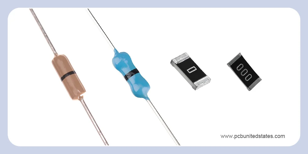
You’ll notice an interesting phenomenon: a 0 ohm resistor isn’t actually zero-resistance, as its name suggests. In fact, it’s a resistor with a resistance approximately equal to zero ohms, almost negligible. There are two types of zero ohm resistors: surface mount technology (SMT) 0 Ω resistors (using one or more zeros to represent resistance) and through-hole 0 Ω resistors (marked with a black symbol).
While the 0 ohm resistor looks similar to standard resistors, its function is quite different. It can solve a variety of circuit and layout problems at extremely low cost and with minimal complexity, providing a range of effective uses.
Why Use a 0 Ohm Resistor?
A zero ohm resistor can be replaced by other alternatives, such as a jumper, single-pole double-throw (SPDT) switch, etc. These alternatives either increase cost, introduce unprecedented complexity, or require more debugging work. In contrast, a zero ohm resistor, with its simplicity and efficiency, has become an important solution for improving circuit flexibility, manufacturability, and cost-effectiveness.
With its small size, it reduces the space occupied by up to 30%, making it ideal for space-constrained, high-density circuit designs. Zero ohm resistors also allow designers to modify layouts without redesigning. Moreover, their price is only $0.002 to $0.01 each, significantly lower than other alternative options. 0 Ohm resistors support automated assembly processes, making them perfect for high-volume production, further improving overall manufacturing efficiency.
Top 11 Uses of 0 Ω Resistors
Learning the importance of a 0 ohm resistor, let’s dive into the top 11 uses of them to gain a complete understanding.
1. Bridging to Enable Single-Layer Routing
Single-layer PCBs are inexpensive, but avoiding trace overlap is challenging work, especially with a large number of components on the board. A 0 ohm resistor can solve this problem effectively. It acts as a physical bridge between circuit points, allowing signal routing over existing traces without adding extra PCB layers. This provides a low-cost method to implement critical connections where routing space is limited.
2. Replacing Jumpers for Automated Production
Zero ohm resistors can replace jumpers to simplify routing, resulting in an organized layout. Besides, they can replace cross-board wires to minimize EMI and signal integrity risks. Jumpers can be used if you apply manual placement and soldering. It’s not a big problem. However, in mass production, pick-and-place machines are typically used, which can process nearly 100,000 SMT components per hour. Compared to manual assembly, which costs $50-100 per hour and takes about 30 seconds per component, pick-and-place machines offer a significant cost advantage.
3. Serving as a Fuse to Avoid Overcurrent
Compared to traces, zero ohm resistors have relatively weaker current-carrying capacity. Under overcurrent conditions, a 0 ohm resistor will melt first, serving as a low-cost fuse to prevent more serious accidents.
4. Protecting Against Reverse Engineering
Adding several zero ohm resistors can significantly confuse those who want to do reverse engineering. Once engineers have drawn the schematic, they need to identify the various components and their functions. The 0 ohm resistors, especially with different colors, packages, and no resistance marking, can complicate this step. This will drive anyone who copies your circuit board crazy.
5. Configuration Options in Multi-Version Products
In multi-version electronic products, the same PCB design is typically used. However, their function between different versions differ in populated components. For example, WiFi-only tablets and WiFi+3G versions typically use the same design, but the WiFi-only version will not have a 3G module soldered on. In such cases, a specific circuit can be completely isolated by installing or not installing a 0 ohm resistor, thereby preventing signal interference from the unassembled circuit.
Zero-ohm resistors are less expensive and more space-saving than DIP switches and jumper headers. These configuration options cannot be changed by end users, but they allow specific features to be enabled or disabled for different product versions during PCB assembly or testing.
6. Single-Point Grounding for Mixed-Signal PCBs
In mixed-signal circuits (containing both analog and digital circuits), analog ground (AGND) and digital ground (DGND) typically need to be separated. A zero-ohm resistor acts as a controllable connection point, connecting AGND and DGND to form a single-point ground.
7. Enabling or Disabling Circuit Options
When you strategically place 0 ohm resistors in the PCB layout, they can be used to enable or disable circuits flexibly. The circuit will not function properly if the 0 ohm resistor is not soldered. Once soldered, the current can flow normally, and the circuit will work.
For example, a chip pin may have a dual purpose, driving a buzzer or an LED. However, these two tasks cannot be performed concurrently. Engineers can selectively install a zero-ohm resistor in either the buzzer circuit or the LED circuit. It can easily configure which function is activated on the same circuit board without changing the overall design.
8. Component Placeholder for Flexible Adjustments
A 0 ohm resistor can often be used as a placeholder, allowing designers to easily populate or omit components as needed later. This flexibility is crucial during prototyping and testing, if adjustments are necessary. The adjustments can be finished without modifying the circuit board layout.
9. Isolating for Testing and Debugging
Remember a critical principle: ensuring the scope of changes or interventions is limited to the smallest practical area. When you need to test and debug a new design, it is challenging work. The functionalities of many installed components are unknown to you. You definitely don’t want circuit 2 to interfere with circuit 1 debugging. In this case, you can use a 0 ohm resistor for isolation.
10. Acting as Inductive or Capacitive Parts
In high-frequency signals, 0 ohm resistor can serve as a capacitor or inductor to assist in solving EMC issues. It’s beneficial for these issues between the power and the IC Pin or between the ground and the ground.
11. Providing a Current Measurement Point
If you want to measure the power consumption of the whole circuit or just a chip, you can connect a 0 ohm resistor in series with the power supply. Once the protoboard is finished, you can remove the resistor to measure the two points with a multimeter. This helps to measure the actual current flow of the chip or entire circuit. In this way, you don’t need to cut the traces on the board, only desoldering the resistor and then resoldering after measuring.
Final Words
The 0 ohm resistor plays a crucial role in modern PCB design. The eleven application examples listed above highlight how 0-ohm resistors can simplify complex circuit designs. By skillfully utilizing it, PCB designers can solve layout, testing, and configuration challenges without redesigning the circuit. Collaborating with an experienced MOKOPCB ensures the effective implementation of these designs.
Zero Ohm Resistor FAQs
1. Is 0 ohms possible?
Definitely impossible. It can be said that there is no resistor with zero resistance. A 0 ohm resistor is marked as 0 ohm because its resistance is so small that it can be almost ignored.
2. What is the value of a zero–ohm resistor?
Depending on the accuracy class, the resistance value of a zero-ohm resistor varies, but it is generally less than or equal to 50mΩ.
3. What is the color code for a 0 ohm resistor?
The color code of a through-hole 0 Ω resistor is a single black band, marking 0Ω.
4. Does 0 ohm mean no continuity?
No, it’s continuity. When the resistance is 0 ohms, it means that current can flow freely. The circuit is continuous. Conversely, if the measurement result shows infinity, it means that the circuit is broken, and current cannot flow. There is no continuity.
5. What is the difference between a wire and a 0 ohm resistor?
As discussed, 0 Ω resistors have many uses, and in some cases, they can replace wires to improve the efficiency of automated production.
