PCB capacitors are critical passive components that are frequently utilized in different circuits. Its function is similar to a battery, but it has a limited electrical energy storage capacity. Due to this property, handling capacitors can be dangerous. Thus, it’s necessary to discharge capacitors properly to avoid potential risks, such as electric shock. Besides, residual voltage stored in a capacitor can result in a high inrush current when it is suddenly connected to other components. The sensitive components, such as ICs and resistors, may easily burn out. In this blog, we will introduce three practical methods to discharge capacitors. Let’s explore to ensure safe circuits.
Why Is It Important to Discharge Capacitors in Circuits?
In electronic circuits, safety and reliability are crucial. Capacitors may hold onto stored energy for a long period even when the power source is cut off. If this residual charge is not properly discharged, it can lead to various potential safety and reliability problems.
Prevents Electric Shock and Safety Hazards: Even though the power is removed, the PCB capacitors can still retain stored energy. If not discharged correctly, residual voltage may cause electric shock during testing, repair, or assembly. This may cause a mild burning or stinging sensation and may even be potentially fatal.
Protects Sensitive Electronic Components: When a charged capacitor discharges suddenly, it may cause damage to sensitive components. Controlled discharge prevents unexpected current surges and helps protect component integrity.
Avoid Accidental Short Circuits: If a charged capacitor accidentally touches PCB traces, it can release energy instantly. This may cause sparks, trace damage, or even board failure. Proper discharge minimizes the risk of accidental short circuits during handling.
How to Discharge Capacitors Safely?
For anyone designing and assembling PCBs, it is crucial to be familiar with the safe handling of PCB capacitors and the potential hazards associated with them.
Firstly, you should check if it’s necessary to discharge capacitors. There are many methods for measuring the capacitance of PCB capacitors, including using a capacitance meter, oscilloscope, or multimeter.
Then, if a discharge capacitor is needed, choose an appropriate method based on the amount of charge it holds. The following are simple steps for measuring capacitance using a multimeter:
- Disconnect the capacitor from the power supply.
- Select the highest DC voltage setting on the multimeter.
- Attach the multimeter probes to the capacitor’s two terminals.
- Determine the reading:
- V < 10 V: No discharge required.
- V ≥ 10 V: Discharge required (electric shock hazard).
Once you’ve determined the reading, you can choose the corresponding methods to discharge capacitors safely.
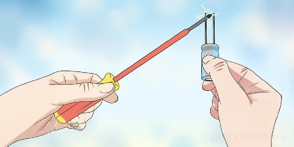
1. Using a Screwdriver to Discharge Capacitors (Medium Voltage, ≤24 V)
When it’s OK:
Voltage ≤24 V and energy ≤0.2 J (IEC ES1 limit).
Example: 1 000 µF @ 12 V = 0.072 J → safe.
Step-by-step:
Step 1: Grip the screwdriver ONLY by the insulated handle. Do not touch the metal part to ensure safety.
Notice: Check if the screwdriver handle is damaged.
Step 2: Hold the capacitor by its sides, grasping the lower end firmly.
Notice: Use your non-dominant hand to hold the bottom of the capacitor in a C-shaped grip, while your dominant hand performs the operation.
Step 3: Bridge capacitor terminals for short circuits with a screwdriver, allowing the remaining charge to release. It may cause a loud bang and a spark.
Notice: You may see and hear the phenomenon of electrical discharge with sparks. Make sure the screwdriver touches both terminals at the same time.
Step 4: Remove the screwdriver, then short-circuit the terminals again and observe if any sparks are produced. Or, re-measure the capacitor’s voltage (target <1 V). If not, repeat the above process to completely release the charge.
Warning: Discharging a capacitor with an insulated screwdriver is a convenient method, but the steps must be followed strictly to ensure safety.
2. Using a Light Bulb to Discharge Capacitors (Medium Voltage, ≤24 V, visual indicator)
Why Choose a Light Bulb?
- Gives visual feedback, dim-to-off as the capacitor discharges.
- Idealfor teaching labs and demonstrations.
Pick a suitable bulb
Considering the voltage rating, power rating, and the resulting resistance.
Example:
- 12 V, 5 W lamp→ R ≈ 30 Ω, I ≈ 4 A
- 24 V, 3 W lamp → R ≈ 190 Ω, I ≈ 125 A
Step-by-step:
Step 1: Connect the light bulb in series with the capacitor with insulated leads or clips. It just serves as a resistor.
Step 2: Observe the bulb brightness. It will flash bright to fade, and finally go dark.
Step 3: Wait until the bulb turns completely off.
Step 4: Remove the bulb and re-measure the capacitor voltage.
3. Using a Bleeder Resistor to Discharge Capacitors (High Voltage, >24 V)
The two methods above are for discharging low-to-medium voltage capacitors. For high-voltage capacitors, using a bleed resistor allows for controlled discharge, ensuring safety.
Step-by-step:
Step 1: Choose a suitable resistor, which will determine the speed of the capacitor discharging. The discharge speed decreases with increasing resistance. However, a higher resistance value can make discharging high-voltage capacitors safer.
Step 2: Connect the two ends of the resistor to the two terminals of the capacitor, forming a path through which the charge can gradually flow out.
Step 3: Await the capacitor’s discharge. The time required depends on the resistance value and the capacitor’s voltage.
Step 4: Wait for a moment, then re-check the capacitor voltage. Repeat the above process if it’s not discharged fully.
How Long Is Needed for a Complete Capacitor Discharge?
Now that we’ve learned three methods to discharge capacitors, it’s also important to know the time required for full discharge. If a capacitor is only partially discharged, it can still be dangerous.
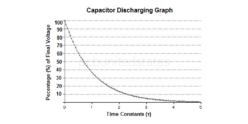
So what determines the discharge time of a capacitor? Exactly, it’s the time constant. The time constant is defined as: T = R × C, with R in ohms (Ω) and C in farads (F). It defines how fast the voltage across a capacitor decreases. The capacitor will typically discharge to nearly zero percent of its initial voltage after five time constants (Rule of 5-τ).
- 1 RC → Voltage drops to about 37% of the initial value
- 3 RC → Voltage drops to about 5%
- 5 RC → Voltage is effectively zero
Example: 100 µF capacitor discharging through a 10 kΩ Resistor
Calculate the time constant: τ=R×C=10000×0.0001=1s
- After 1 s (≈ 1 RC): Voltage drops to ~110 V (≈37% of initial)
- After 3 s (≈ 3 RC): Voltage drops to ~15 V (≈5% of initial)
- After 5 s (≈ 5 RC): Voltage drops to ~2 V (nearly fully discharged)
Safety Warning: Even after the calculated discharge time has elapsed, it is necessary to use a multimeter to take measurements. The actual discharge time is affected by various factors, such as the type of capacitor, leakage current, and resistance.
Last Words
It’s important to discharge capacitors safely, preventing any accidents. Whether you choose a bleeder resistor discharge, shorting with a screwdriver, or using a light bulb, always follow proper procedures and verify the voltage with a multimeter after discharging. Besides, understanding the capacitor’s time constant is essential to ensure sufficient discharge time.
