File Requirements for PCBA
PCB Assembly Capabilities
To ensure the highest quality and precision in your PCB Assembly (PCBA) project, MOKOPCB requires specific documentation files that enable our team to deliver accurate and efficient assembly services.This article lists all necessary file requirements for PCBA and recommendations needed to complete a project successfully.
Mandatory File Requirements for PCBA
- Bill of Materials (BOM)
The Bill of Materials is the foundation of your PCBA project that has a list of all the components needed to assemble. This is a critical document that ensures accurate sourcing of parts and proper positioning of components.
Accepted File Formats: .xls, .xlsx, .csv
Submission Format: Single file or compressed archive (.zip or .rar)
For Consigned/Kitted Orders
Your BOM must include the following information:
Line Number: Sequential identification for each component entry
Quantity: Required number of parts per PCB assembly
Reference Designator: Component location identifier (e.g., R1, C2, U4, Q1)
Part Number: Your internal or preferred part number
Component Description: Clear and detailed part description
Package Type: Component mounting style (Surface Mount, Through-Hole, or Mixed)
Component Value: Electrical specifications where applicable
For Turn-Key and Partial Turn-Key Orders
Include all consigned order information plus:
Manufacturer Name: Official component manufacturer
Manufacturer Part Number (MPN): Exact manufacturer part number
Distributor Information: Preferred supplier and distributor part numbers
Substitution Notes: Acceptable alternative parts if applicable
- Gerber Files
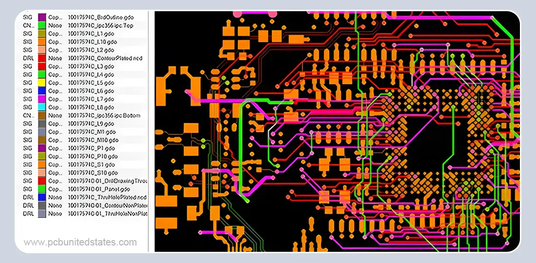
PCB assembly requires Gerber files in standard RS-274X format. It is necessary that these files are the same as the files that are used in your PCB manufacturing so that the alignment and component placement are perfect.
File Format: RS-274X Extended Gerber or Gerber X2 (preferred for advanced features)
Submission Format: Compressed archive (.zip or .rar)
Required Gerber Layers
Essential Layers:
Silkscreen Layers: Component outlines, reference designators, and assembly markings
Copper Layers: All conductive traces, pads, and plane layers
Solder Paste Layers: Stencil data for surface mount component soldering
Solder Mask Layers: Component exposure and protection areas
Additional Recommended Layers:
Drill files (.drl or .xln) for accurate hole placement
Fabrication notes and dimensional drawings
Assembly notes and special markings
- Centroid File (Pick and Place Data)
The Centroid file contains detailed positioning information for our automated assembly machines, thus ensuring accurate component placement and orientation.
Also Known As: Pick-and-Place file, XY Data, Insertion file, or Component Placement file
File Format: .csv, .txt, or .xls
Submission Format: Compressed if multiple files (.zip or .rar)
Required Centroid Data:
Reference Designator: Component identifier matching BOM and silkscreen
X-Coordinate: Horizontal placement position (in specified units)
Y-Coordinate: Vertical placement position (in specified units)
Rotation Angle: Component orientation in degrees
PCB Side: Top or Bottom layer designation
Important Note: Centroid files should only include Surface Mount Technology (SMT) components. Through-hole components are assembled using manual processes guided by assembly drawings and silkscreen references.
Recommended Supporting Documentation
Although not required, these additional documents will greatly improve the quality of the assembly and decrease the possibility of manufacturing problems:
Assembly Drawings
Detailed visual representations of component placement
Critical dimension specifications and tolerances
Special assembly sequence requirements
Component polarity and orientation guidelines
Special Assembly Instructions
Unique handling procedures for sensitive components
Custom soldering or attachment requirements
Post-assembly testing and validation procedures
Programming instructions for microcontrollers or programmable devices
Reference Materials
High-resolution photographs of correctly assembled PCBs
Detailed images of critical assembly areas
Before and after assembly comparisons
Component identification and verification photos
You can submit your files directly through our secure online portal or by sending them to sa**@************gy.com
Engineering Support to Maximize Your File Accuracy
Our experienced engineering team is ready to support you with file format conversion, BOM optimization, component sourcing guidance, DFA recommendations, and custom assembly consultations. From the initial file review to final inspection and testing, we follow the highest quality standards throughout the whole PCBA process. MOKOPCB is committed to partnering with you on your next PCBA project and ensuring outcomes that exceed your expectations.
Contact Us
Got any questions or inquiries? Fill out the form and we will get back to you soon