PCB Electrical Testing
From smartphones and medical devices to automotive systems and aerospace technology, nearly every electronic product relies on a PCB to function reliably. But before a board ever makes it into a finished product, it must undergo electrical test.
PCB electrical testing is more than a box to check in the manufacturing process – it’s a safeguard against hidden defects, costly recalls, and product failures in the field. Here, we have summarized the fundamentals in this guide, what PCB electrical testing is, why it is important, the most popular testing methods and how to create boards that are simple to test.
What Is PCB Electrical Testing?
PCB electrical testing, also known as PCB E-test, is the process of verifying that a circuit board is free from electrical defects and performs as intended. These tests look for issues such as:
- Opens (missing or broken connections)
- Shorts (unwanted connections between nets)
- Incorrect values (resistors, capacitors, or embedded components out of spec)
- Miswiring or misplacement (nets connected to the wrong pads)
Testing typically happens at two key stages:
Bare board testing
After the PCB is manufactured but before components are assembled, electrical test is carried out. Its purpose is to ensure that the raw PCB matches the netlist and is free of shorts, opens, or via failures.
Assembled board testing
Once components are assembled on the board, engineers perform electrical testing again. This ensures that the populated PCB functions as designed.
With the early detection of defects, manufacturers can eliminate costly rework and only send out good boards.
Why PCB Electrical Testing Matters
- Improves Quality and Reliability
All tested boards are checked against the design netlist, which means that the finished product has electrical integrity required to operate consistently.
- Reduces Manufacturing Costs
Early identification of errors prior to assembling prevents costly scrap and rework. A faulty bare board is much more cheaper to repair than an already assembled board.
- Meets Industry Standards
Automotive, aerospace and medical industries require thorough test documentation and traceability for safety-critical applications. And PCB E-test provide the data required for regulatory compliance and market access.
- Supports Faster Time-to-Market
Fast troubleshooting is achieved through effective electrical test, which helps reduce the product launch delay by detecting problems early in the design cycle and enables faster and smoother development cycles.
The Most Common Types of PCB E-test
There are dozens of testing methods available, but in practice, only a few dominate PCB manufacturing due to their effectiveness and efficiency. The most widely used are:
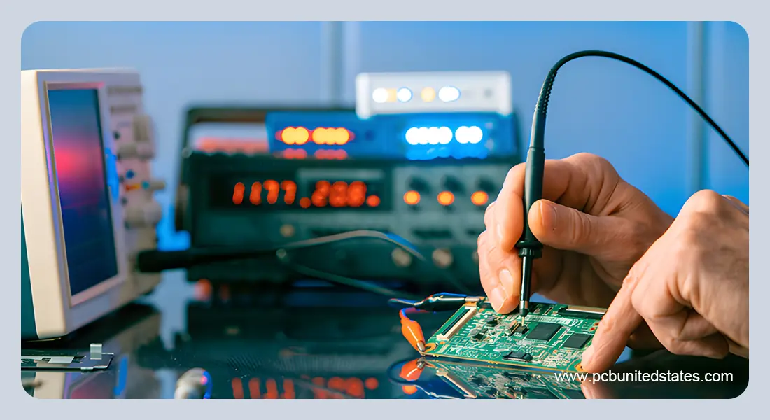
- Flying Probe Testing (FPT)
Flying probe testing uses movable probes that “fly” around the board to touch test points. It requires no dedicated fixture, making it ideal for:
Prototypes and low-volume runs (cost-effective).
Boards with frequent design changes.
High-precision testing on fine-pitch designs.
The trade-off? Flying probe is slower than fixture-based testing, so it’s less suitable for very high-volume production.
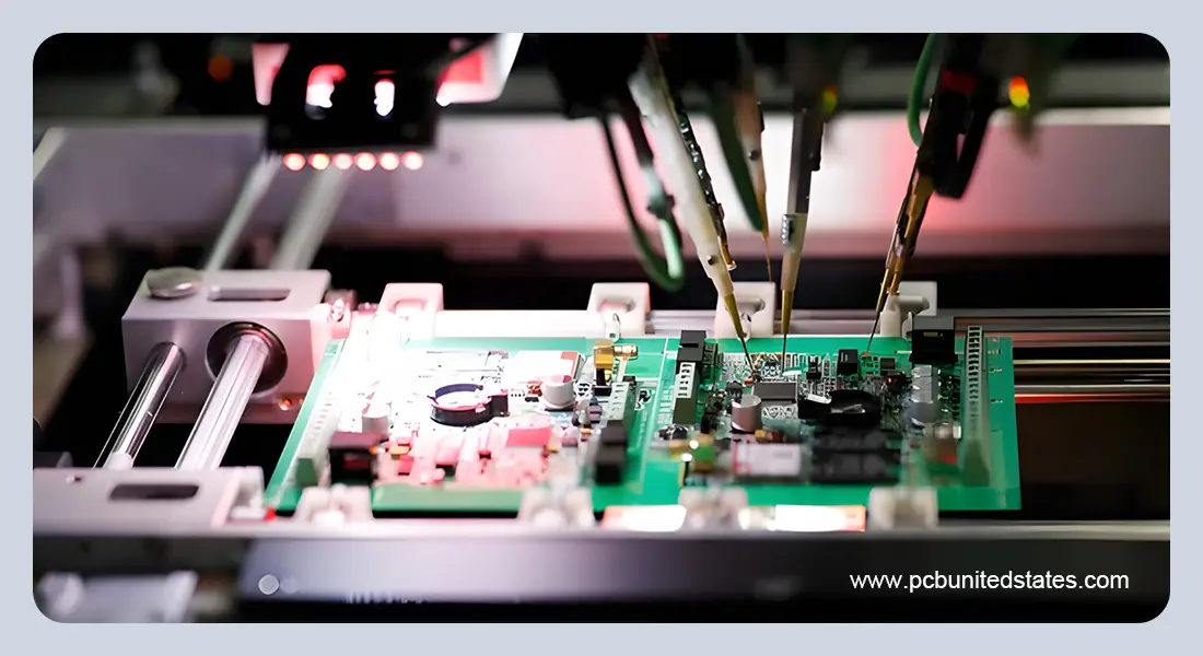
2. Bed-of-Nails (Fixture) Testing
This method uses a custom test fixture with hundreds or thousands of spring-loaded pins that contact the board simultaneously. It is best for:
High-volume production, where speed matters.
Testing many nets at once.
Delivering consistent and repeatable results.
The downside is the high upfront cost of building the fixture, which only pays off if you test large batches of the same design.
- In-Circuit Testing (ICT)
Once components are assembled, ICT checks that each one is present, correctly oriented, and electrically functional. It is a powerful way to catch solder bridges, missing parts, or faulty components before boards move on to functional testing.
- Functional Testing (FCT)
Functional testing is used to emulate the actual operating environment and to ensure that it works as expected. It is the final stage of PCB testing, ensuring that the board can be used in practice and not just on paper.
- Boundary Scan Testing (JTAG)
This technique measures digital circuits using the built-in testing features of the compatible integrated circuits. It allows checking internal connections and component performance through standard test access ports.
- Continuity Testing
Continuity testing is a fundamental PCB electrical test that ensures a complete electrical connection between two points and confirms all connections are properly established. It can help to verify the component and layer connection, and identify defects like broken traces or incomplete vias, as well as maintain the integrity of ground or power planes.
Best Practices for Reliable PCB Electrical Testing
Early design collaboration: Design cooperation at the beginning of the design process can eliminate expensive re-designs and design testing delays. During the development of test programs, manufacturers can identify potential test difficulties and propose design improvements.
Always provide a netlist: A netlist provides the electrical connectivity reference that test equipment uses to verify the manufactured PCB matches your original design intent and enables automated testing.
Clarify test requirements: Clearly document all important nets, voltage/current tolerances, and expected performance requirements. This not only makes sure engineers and operators know precisely what is to be checked but also minimizes the chances of missing defects during testing.
Choose reliable surface finish: A stable surface finish like ENIG or OSP helps increase probe contact and measurement consistency to reduce false failures. Do not use rough or uneven finishes that may reduce accuracy of the tests.
Check fixture design: During in-circuit testing (ICT), pin mapping and alignment should be reviewed thoroughly prior to production. Proper fixture verification helps to avoid incorrect contact points, reduce errors in setups and saves time during the testing.
PCB Electrical Testing at MOKOPCB
At MOKOPCB, we recognize that precise and thorough electrical testing is essential to delivering high-quality PCBs. Our cutting-edge test equipment, such as flying probe testers, bed-of-nails testers, X-ray equipment allow us to find even the smallest defects. We adapt our testing procedures to each PCB design, ensuring critical connections and components are thoroughly verified.
Electrical tests are done at various stages of production-from bare board inspection to final functional testing- ensuring reliability at each step. Combined with thorough data analysis and comprehensive reporting, our strategy will provide every PCB with the highest standards of performance and quality.
Contact Us
Got any questions or inquiries? Fill out the form and we will get back to you soon