PCB Milling
What Is Milling in PCB Fabrication?
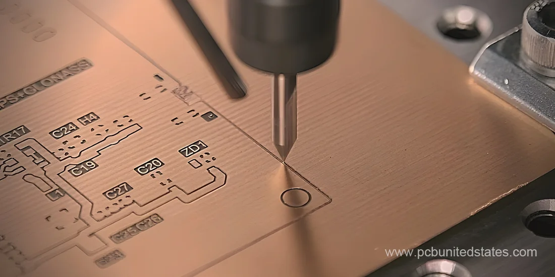
PCB milling, or isolation milling, is a controlled depth routing process used to remove certain areas of copper and printed circuit board material to form circuit patterns. It is a subtractive manufacturing technique that involves using computer-controlled cutting tools to carve out signal traces, pads, and structures directly from copper-clad boards according to digital PCB layout files.
Printed circuit board milling can be used to create component recesses, pocket mill, and create fully plated conductive structures that connect multiple layers and form heat sink cavities. It is a non-chemical process, which does not require exposure to dangerous chemicals and can safely be conducted even in regular offices or laboratories. And the quality of milling PCB boards is dependent on milling accuracy, system precision as well as milling bit conditions.
Milling Tool Sizes and Profile Design Specifications
The smallest cutting tool available for milling operations measures 0.8mm in diameter, while the conventional tool size is 2.0mm. Special custom tools are also offered whose diameters range from 0.8mm to 2.0mm as documented in the specifications table below.
| Design Parameter | Value |
|---|---|
| Minimum mill tool diameter | 0.8mm |
| Standard mill tool diameter | 2.0mm |
| Special mill tool diameter | 0.8mm ≤ Ø ≤ 2.0mm |
The internal and external board profiles are machined to meet specific customer requirements. The profiles of the external corners can be manufactured to have sharp angles of 90 degrees or the radiused corners according to the choices that clients have. Internal profile corners, on the other hand, need to have the minimum radius that corresponds to the cutting tool’s radius dimension. The process of cutting PCB profiles as well as creating internal cavities usually follows established machining protocols.
PCB Milling Process: Key Factors and Tips
- CNC PCB milling process normally takes half an hour; however, factors such as the diameter of the cutting tool, size of the board, number of parts, and alignment will affect the process.
- Milling is a non-chemical, clean, and non-toxic operation with quick processing of different boards under laboratory conditions.
- The accuracy of milling and hardness of the tool used will directly influence the performance of the PCB.
- The cutting bit rotation speed does not significantly affect board quality and accuracy.
- New users are required to train on milling techniques before producing PCBs.
- To achieve better quality and accurate results, taking precautionary measures before production is necessary.
- Two software types exist: Raster and Vector systems. And software that relies on raster calculations is generally less efficient than vector-based software because it operates using raster data.
3 Methods to Mill PCB Boards
Three different approaches can be used to carry out the circuit board milling according to different requirements, including Laser, CNC router and Carbide end mills.
- Laser milling
Laser milling is the non-contact method in which a high-powered laser beam is employed to cut, engrave, or mark the circuits board materials with high accuracy. There are some important steps that are included in its process namely, beam generation, beam focusing, heating and melting of the material, ejection of the molten material, and precision beam movement. It is well-suited in those applications where the geometric precision is critical, e.g. RF and microwave PCBs. This technique features low energy consumption, minimal wear and tear, high precision, and requires no drill bits. In spite of being environmentally safe and effective, this method is usually more costly.
- CNC router
CNC routers are computer-controlled machines that hold a router or spindle to do the cutting. Depending on the operational needs, these machines may either have a movable gantry design or a stationary bridge configuration with the working platform moving beneath the spindle. Additionally, there are portable forms where operators locate the machine manually and the CNC system carries out accurate cutting modifications.
Computer-aided manufacturing (CAM) software generates a visual representation of the circuit board and creates the cutting routes that the machine will follow when fabricating the board. The spindle operates along three axes (X, Y, and Z coordinates). These routing systems usually utilize three motors using either servo motor or stepper motor technology.
- Carbide End Mills
Carbide end mills are high-precision cutters that are made of pure solid carbide material. These tools find broad application in engraving, sign making, graphite electrode machining, PCB prototyping, and fiberglass processing. Being a kind of milling cutter, they can be used to support a variety of processes such as profile, face, tracer, and plunge milling. Additionally, carbide end mills are particularly useful in axial cutting tasks and have excellent performance because of the hardness and wear resistance of carbide.
Benefits of Printed Circuit Board Milling
- PCB milling is an environmentally friendly method, as it doesn’t involve the use of harmful chemicals, making it a safer and cleaner option.
- CNC PCB milling machines offer versatility by performing multiple tasks such as milling, drilling, and cutting, all in one setup.
- The flexibility to switch out milling bits based on specific needs allows for greater precision and customization during the milling process.
- In situations where the wet etching method cannot be used to meet the necessary accuracy or form, and where a manual drilling procedure would have to be used otherwise, PCB milling can be beneficial. Milling makes the process easier, saves on additional actions, and may bring the general cost of some designs down.
PCB Milling vs. Etching: Which Should You Choose?
Printed circuit board milling and etching are two commonly used methods to create patterns on a PCB. However, they are very different in the process and applications. Circuit board milling is non-chemical process that uses CNC machines to remove unwanted copper from a board, suitable for prototyping and projects that have restrictions on the use of chemicals. While etching, on the contrary, is a chemical process that uses acids or etchants to dissolve the copper, providing high precision and smooth traces. Therefore, the choice between these two methods should be based on your exact project requirements; milling is cleaner and environmentally friendly but etching is fast and suitable for mass production.
PCB Milling at MOKOPCB
Equipped with state-of-the-art CNC milling equipment, MOKOPCB can manufacture precision circuit boards with high accuracy and excellent surface finish quality. To guarantee that every milled PCB is high-quality and meets the utmost industry standards, our quality control ensures that each PCB meets high industry standards through a clean, chemical-free manufacturing process. For inquiries or to discuss your specific project requirements, feel free to reach out to us! We’re here to help you find the optimal solution for your circuit board needs.
Contact Us
Got any questions or inquiries? Fill out the form and we will get back to you soon