China RF Microwave PCB
$62.90
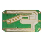
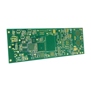
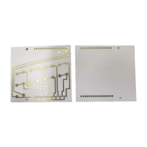
China RF Microwave PCB handles high frequencies operating in the RF and microwave ranges(300 MHz to 300 GHz). Radiofrequency (RF) PCBs typically operate around 3 kHz to 300 GHz, while microwave PCBs generally deal with 3 MHz to 3 GHz. Base stations, radar, GPS, 5G, and other high-frequency applications use such PCBs.
Shipping fee and delivery date to be negotiated. Send inquiry for more details.
Your payment information is processed securely. We do not store credit card details nor have access to your credit card information.
Claim a refund if your order is missing or arrives with product issues, our support team would deal with your refund within 24 hours.
| Layer Counts | 8L |
| Base Material | Rogers |
| Board Thickness(mm) | 1.2mm |
| Max board size(mm) | 570*670mm |
| PCB size tolerance | ±0.2mm |
| Min. Hole Size | 0.15mm |
| Min. Line Width | 4mil |
| Copper Weight | 1oz |
| Surface Finish | ENIG |
| Certificate | UL, RoHS, ISO, ISO9001, ISO13485, IPC610, and REACH |
 China RF Microwave PCB
| 5 star | 0% | |
| 4 star | 0% | |
| 3 star | 0% | |
| 2 star | 0% | |
| 1 star | 0% |
Sorry, no reviews match your current selections
Questions & Answers
1. What is your lead time?
1-2 days. We have our own warehouse and stock in large quantities.
2. Where does MOKOPCB ship from and to?
We deliver our goods from our facilities in Shenzhen, China.
3. What quality certifications do you have?
We have certified UL, ISO, RoHS, IPC, etc.
4. What Rogers material is best for RF and microwave PCBs, and why?
Rogers such as RO4350B is preferred in the RF and microwave applications because they are featured with excellent electrical properties, low dielectric loss with a low Df, and stable dielectric constant across frequencies. The low moisture absorption and thermal stability also make it suitable for high-frequency applications.
5. Why does PCB surface roughness matter for RF performance?
Surface roughness matters for RF performance because it affects signal integrity. A rougher surface increases conductor losses, while a smoother surface reduces resistance and insertion loss. Excessive roughness also impacts Dk consistency and causes phase distortions.
6. What’s the minimum via thickness of the RF and microwave PCB you can produce?
The minimum via thickness for through hole vias we can produce is an average of 25um; for blind and buried vias is an average of 20um.
7. Why do RF PCBs require tighter copper weight tolerances?
RF PCBs require tighter copper weight tolerances in that copper thickness directly impacts trace impedance. Controlled copper weight ensures uniform Dk, reduces mismatch, and maintains performance in RF and microwave circuits.
8. What is the acceptable dielectric thickness variation for RF PCBs?
For RF PCBs, the dielectric thickness had better stay within ±5–10% of the specified value. Tight dielectric thickness can prevent impedance mismatch and ensure Dk consistency. Or it is easy to affect signal integrity and resonance tuning.
9. Can China manufacturers provide RF PCBs at a lower cost?
Yes, we can offer you a more affordable price on RF PCBs.
10. What causes insertion loss in RF PCBs?
The insertion loss in RF PCB is mainly caused by 3 factors: conductor loss(copper roughness and skin effect), dielectric loss, and radiation loss(impedance mismatches).


