High Frequency PCB for Radar Systems
$100.50
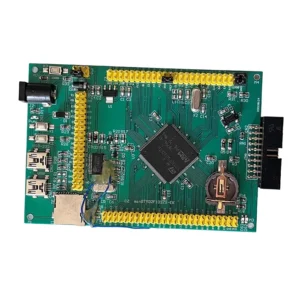
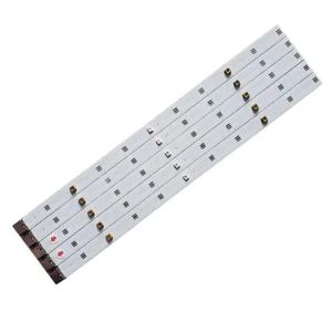
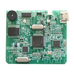
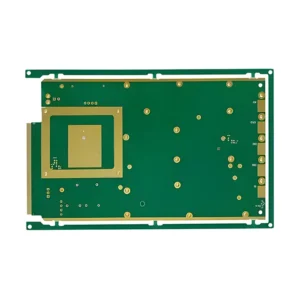
As a crucial component in radar systems, high-frequency PCB offers low insertion loss, robust thermal management, and tight impedance control in modern radar systems to emit and capture radio waves for faster and accurate object detection and tracking. Such high-frequency PCBs are prevalent in radar applications like military radar, weather monitoring, and automotive ADAS.
Shipping fee and delivery date to be negotiated. Send inquiry for more details.
Your payment information is processed securely. We do not store credit card details nor have access to your credit card information.
Claim a refund if your order is missing or arrives with product issues, our support team would deal with your refund within 24 hours.
| Layer Counts | 6L |
| Base Material | Rogers |
| Board Thickness(mm) | 1.6mm |
| Max board size(mm) | 570*670mm |
| PCB size tolerance | ±0.2mm |
| Min. Hole Size | 0.15mm |
| Min. Line Width | 4mil |
| Copper Weight | 2oz |
| Surface Finish | ENIG |
| Certificate | UL, IPC-6012, RoHS, ISO 9001, ISO14001 |
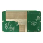 High Frequency PCB for Radar Systems
| 5 star | 0% | |
| 4 star | 0% | |
| 3 star | 0% | |
| 2 star | 0% | |
| 1 star | 0% |
Sorry, no reviews match your current selections
Questions & Answers
1. Does MOKOPCB support mass production?
Yes, we have the capacity to handle small to high-volume PCB production with automated assembly lines.
2. What are your payment terms?
T/T, Paypal, Western union, L/C, ESROW.
3. How does substrate material affect signal propagation speed in high-frequency PCB for radar systems?
The speed of signal propagation depends on the substrate’s dielectric constant(Dk). Lower DK means faster propagation and lower signal delay, which is preferred for high-speed radar signals; that’s why FR4 (higher Dk) is not recommended for HF PCB.
4. Why is Rogers commonly used for radar HF PCB?
Rogers materials offer low signal loss, stable Dk, and superior thermal management, which is just what high-frequency radar applications require.
5. What’s the role of vias used in HF radar PCBs? How to design these vias?
In HF PCB, vias should be used carefully to ensure proper grounding, thermal management, and signal integrity. When designing HF PCB vias, we will optimize via placement and use back drilling for important traces to keep signal integrity, and ensure vias are minimal and well-placed in RF paths for better performance.
6. How does temperature affect radar PCBs?
Temperature fluctuations may lead to material expansion(Rogers is more stable), signal drift, component reliability, and phase stability.
7. Can you produce flexible substrate for the radar HF PCB?
Yes, we can produce flexible substrates for HF PCB. Flexible HF PCBs are feasible for radar systems that require conformal designs, like drones, wearables.


