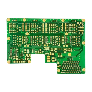
Rigid-flex RF Microwave PCB
$73.90
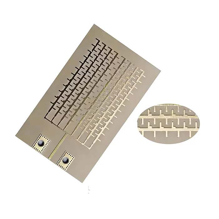
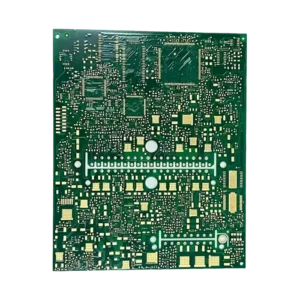
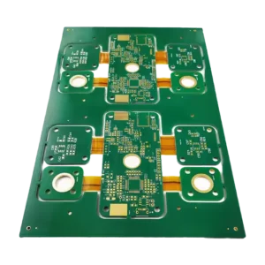
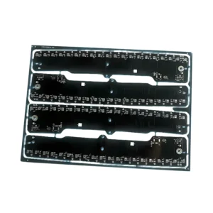
Rigid-flex RF microwave PCB is a hybrid circuit board that incorporates rigid and flexible laminates with adhesive bonding filmsdevlivering both superior high-frequency performance and mechanical flexibility. This cutting-edge PCB is designed for applications requiring signal integrity, durability, flexibility, and compact integration, such as radar and antenna systems, 5G mmWave devices, ADAS, RF devices, and so on.
Shipping fee and delivery date to be negotiated. Send inquiry for more details.
Your payment information is processed securely. We do not store credit card details nor have access to your credit card information.
Claim a refund if your order is missing or arrives with product issues, our support team would deal with your refund within 24 hours.
| Layer Counts | 6L |
| Base Material | Polyimide + Rogers |
| Board Thickness(mm) | 2.0mm |
| Max board size(mm) | 570*670mm |
| PCB size tolerance | ±0.2mm |
| Min. Hole Size | 0.1mm |
| Min. Line Width | 4mil |
| Copper Weight | 2oz |
| Surface Finish | ENIG |
| Certificate | UL, RoHS, ISO, ISO9001, ISO13485, IPC610, and REACH |
 Rigid-flex RF Microwave PCB
| 5 star | 0% | |
| 4 star | 0% | |
| 3 star | 0% | |
| 2 star | 0% | |
| 1 star | 0% |
Sorry, no reviews match your current selections
Questions & Answers
1. What is your lead time?
1-2 days. We have our own warehouse and stock in large quantities.
2. What alternate surface finishes are available?
Beyond standard HASL, we also provide those surface finishes: ENIG, OSP, Immersion Silver, ENPIG, and Immersion Tin.
3. How do I minimize loss when signals pass from rigid to flexible?
To reduce signal loss during transitions, designers need to ensure impedance continuity by matching trace widths and using compatible materials like Rogers.
4. What’s the minimum copper thickness for the rigid-flex board you can achieve?
The minimum thickness we can achieve is 0.1mm. 0.3mm for a 4-layer board and 0.8mm for a 10-layer board.
5. What’s the peel strength of your rigid-flex RF microwave PCB?
The peel strength of our rigid-flex RF PCBs typically meets≥1.4N/mm for reliable adhesion and durability.
6. What other base materials can be used in a rigid-flex circuit board?
The rigid sections can use low-loss RF materials like FR4, Rogers, Taconic, or Isola. The Flex section can use polyimide and Rogers ULTRALAM 3850.
7. How Does Flexibility Affect RF Performance of Rigid-Flex PCB?
For RF microwave rigid-flex PCBs, the flexibility may introduce impedance instability as bending the PCB may alter trace geometry, leading to impedance mismatches. What’s more, flexible polymide materials have higher insertion loss and impact signal integrity with a heightened crosstalk in dense layouts.
8. Why use rigid-flex RF PCBs over rigid or flexible PCBs?
Rigid-flex PCBs excel over rigid or flexible ones because they combine both high-frequency performance and seamless 3D packaging. It meets high-frequency needs and provides dynamic bending without sacrificing the rigidity needed, making it practical in various RF and microwave devices.
9. For a 6-layer rigid-flex PCB, what’s the distribution of rigid laminates and flexible laminates?
In a typical 6-layer rigid-flex PCB, the rigid laminate sections may have 4-6 layers, and the flexible laminate sections may have 1-2 key layers in bend zones. L3-L4 bending areas usually set the flex core and sometimes set the rigid layer if needed. Outer L1 & L6 and inner L2 & L5 are always rigid laminates.

